Introduction
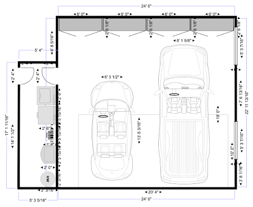
Designing your dream home or renovating an existing property is exciting, but getting the technical details right can feel overwhelming. If you are wondering how to draw a garage door in a floor plan correctly, you are not alone; many homeowners and junior drafters struggle with the specific symbols and dimensional standards required for professional-looking blueprints. This guide breaks down the process into simple, actionable steps so you can create accurate, code-compliant plans with confidence.
Understanding Standard Garage Door Dimensions
Before you put pencil to paper or click your mouse, you must understand the physical reality of what you are drawing. A floor plan is not just art; it is a set of instructions for builders. Drawing a door that doesn’t exist in real life will cause costly change orders later.
According to industry standards, residential garage doors typically follow these dimensions:
- Single Car Garage Door: 8’ x 7’ or 9’ x 7’ (Width x Height)
- Double Car Garage Door: 16’ x 7’ or 18’ x 7’
- RV/Boat Garage Door: 10’-12’ wide x 10’-14’ high
Why Dimensions Matter in Drafting
When learning how to draw a garage door in a floor plan, accuracy prevents construction errors. The rough opening (RO) must be slightly larger than the actual door size to accommodate tracks, springs, and shimming. Always verify manufacturer specifications before finalizing your drawing. For foundational knowledge on architectural scales and drafting conventions, referencing resources like Wikipedia’s article on Architectural Drawing provides excellent context on standardized representation methods used globally.
Step-by-Step: How to Draw a Garage Door in a Floor Plan Manually
If you are drafting by hand using vellum and an architect’s scale, precision is paramount. Follow this concrete workflow:
- Determine Your Scale: Most residential floor plans use 1/4″ = 1′-0″. Ensure your ruler matches this scale.
- Locate the Wall: Draw the exterior wall lines first. Standard garage walls are often 2×6 framing, meaning the wall thickness should be drawn at 5.5 inches (actual) or scaled accordingly.
- Mark the Rough Opening: Measure from a known reference point (like a corner). For a 16′ double door, mark exactly 16′ on the wall line. Use light construction lines initially.
- Draw the Door Symbol:
- Erase the wall line between your marks.
- Draw a thin line representing the door panel flush with the interior or exterior face (depending on mount).
- Add dashed lines perpendicular to the wall to indicate overhead track clearance or swing arc if applicable.
- Label Clearly: Write “GD” or “OVERHEAD DOOR” with dimensions (e.g., “16’x7′ OH”). Include a tag number like “G-01” that references your door schedule.
- Indicate Operation Direction: Use arrows to show whether the door rolls up, swings out, or slides. Upward roll-up is standard; denote this with a vertical arrow pointing up inside the opening.
Pro Tip: Always leave at least 12 inches of wall space beside the garage door opening for structural framing and hardware mounting. Drawing the door flush against a perpendicular wall is a common rookie mistake that makes installation impossible.
Digital Drafting: Using Software to Draw Garage Doors
Most modern drafting happens digitally. Whether you use AutoCAD, Revit, SketchUp, or Chief Architect, the principles remain consistent, but the tools differ.
Common Software Workflows
| Software | Tool/Command | Key Setting to Check |
|---|---|---|
| AutoCAD | DOOR or Dynamic Block | Verify block scale matches drawing units |
| Revit | Door Family > Overhead Door | Set Rough Width & Height parameters |
| SketchUp | Component > Garage Door | Adjust lens/focal length for proper scaling |
| Chief Architect | Build > Door > Garage Door | Auto-generates framing header |
Critical Digital Settings
When figuring out how to draw a garage door in a floor plan digitally, never assume default settings are correct. Many CAD libraries default to commercial sizes. Always:
- Override family types to match residential standards.
- Check layer assignments. Garage doors should be on a dedicated “A-DOOR-GARAGE” layer, not generic walls.
- Enable annotation scaling so text and symbols remain legible at different viewports.
- Verify snap points. Misaligned snaps create gaps that confuse contractors during takeoffs.
Decoding Garage Door Symbols and Annotations
Professional blueprints communicate through universally recognized symbols. Misinterpreting these leads to built-in obsolescence.
Standard Symbol Elements
- Solid Line Across Opening: Represents the closed door panel position.
- Dashed Lines Above/Below: Indicate headroom requirements for torsion springs and tracks (typically 12″-18″ above opening).
- Swing Arc (Quarter Circle): Only used for side-hinged carriage house doors, not sectional overhead doors.
- Centerline Symbol (CL): Marks the center of the opening for electrical outlet placement and opener alignment.
Annotation Best Practices
Your drawing must include more than geometry. Add these data points directly on the plan or in a referenced schedule:
- Fire Rating: If attached to living space, note “20-min FD” or as required by local code.
- Insulation Value: Specify R-value (e.g., “R-16 INSULATED”) for energy compliance.
- Opener Provision: Note “PROV FOR AUTO OPENER” with electrical outlet location.
- Threshold Detail: Reference a detail bubble showing weather seal and slab edge treatment.
Common Mistakes to Avoid When Drawing Garage Doors
Even experienced designers slip up. Watch for these pitfalls:
- Ignoring Header Depth: Failing to account for the structural header above the door reduces usable headroom. Standard headers are 12″-18″ deep depending on span.
- Forgetting Side Clearance: Torsion spring systems require 4″-6″ of clear wall space on each side. Extension springs need even more.
- Misplacing Electrical Outlets: Openers need power inside the garage, centered above the door, typically 10′-12′ from finished floor. Don’t hide outlets behind drywall where tracks mount.
- Wrong Swing Direction Notation: Sectional doors go up, not out. Using a swing arc symbol implies outward swing, which violates most setback codes and creates safety hazards.
- Scaling Errors in Print: Printing at “Fit to Page” instead of true scale renders dimensions useless. Always print test sheets at 100% scale and measure with a ruler.
Frequently Asked Questions (FAQ)
What symbol represents a garage door on a floor plan?
A garage door is typically shown as a solid straight line across the wall opening, often accompanied by dashed lines indicating overhead track space. Unlike entry doors, it does not have a quarter-circle swing arc unless it is a rare side-hinged model. Always pair the symbol with a label (“OH DOOR”) and dimensions.
How much wall space do I need beside a garage door?
Minimum 12 inches of stud-framed wall space is recommended on each side of the rough opening. This accommodates jack studs, king studs, track brackets, and spring hardware. Tighter clearances may work with specialized low-headroom hardware but should be verified with the door manufacturer before drawing.
Should I draw the garage door open or closed in a floor plan?
Always draw garage doors in the closed position. Floor plans represent the building envelope and spatial boundaries. Showing the door open misrepresents the conditioned space boundary and confuses area calculations. Use annotations or separate detail views to illustrate operation mechanics.
Do I need to show the garage door header in a floor plan?
While the header itself isn’t drawn in plan view (it appears in sections/elevations), you must account for its depth. Note the required headroom clearance above the opening (usually 12″-18″) via annotation. Structural engineers or framers determine exact header sizing, but your plan must flag the constraint.
Can I use a standard door symbol for a garage door?
No. Standard door symbols imply hinged, swinging operation. Garage doors operate vertically or horizontally on tracks. Using incorrect symbols causes contractor confusion and potential code violations. Always use manufacturer-specific blocks or clearly annotated custom symbols labeled “OVERHEAD” or “ROLL-UP.”
What scale is best for drawing garage doors in residential plans?
1/4″ = 1′-0″ is the industry standard for residential floor plans. This scale balances readability with sheet size efficiency. At this scale, a 16′ garage door measures exactly 4 inches on paper—large enough to annotate clearly while fitting typical 24″x36″ sheets. Smaller scales (1/8″) make detailing difficult; larger scales (1/2″) waste paper.
Conclusion
Mastering how to draw a garage door in a floor plan bridges creative vision and buildable reality. By respecting standard dimensions, using correct symbols, avoiding common spatial errors, and annotating thoroughly, you transform abstract ideas into actionable construction documents. Remember: every line you draw carries responsibility for safety, function, and budget.
Whether you’re sketching by hand or modeling in BIM, precision builds trust with contractors, inspectors, and future homeowners. Take pride in getting these details right—they’re the invisible foundation of great architecture.
Found this guide helpful? Share it with fellow DIYers, architecture students, or home designers on Pinterest, LinkedIn, or Facebook! Tag us in your floor plan projects—we love seeing accurate drafts come to life. Happy designing! 🏡✏️
Leave a Reply