Introduction
Is your Chamberlain garage door opener acting erratically, refusing to respond to remotes, or displaying mysterious error codes? You are likely dealing with a failed circuit board, and learning how to replace logic board on Chamberlain garage door opener is the most cost-effective solution to restore functionality without buying a new unit. This guide walks you through the diagnosis and replacement process safely, saving you hundreds of dollars in service calls while getting your garage back to normal operation.
What Is a Logic Board and Why Does It Fail?
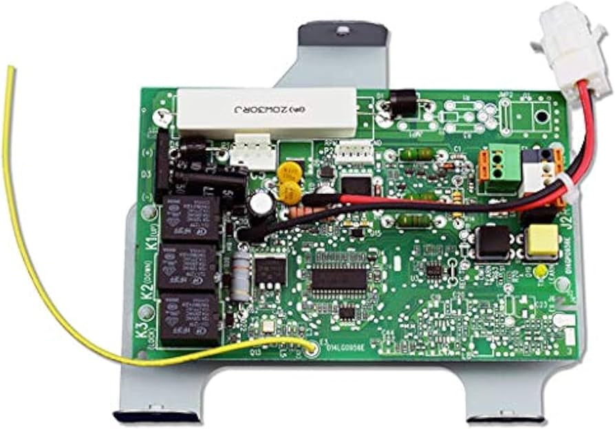
Before grabbing a screwdriver, it is vital to understand what component you are actually replacing. The logic board (often called the motherboard or circuit board) is the “brain” of your Chamberlain garage door opener. It processes signals from your remote, keypad, safety sensors, and wall console to operate the motor safely.
According to technical documentation referenced in general electronics repair literature on Wikipedia, printed circuit boards in residential appliances typically have a lifespan of 10–15 years, though environmental factors can shorten this significantly.
Common Causes of Logic Board Failure
- Power Surges: Lightning strikes or grid fluctuations are the #1 killer of garage door logic boards.
- Moisture and Humidity: Garages are unconditioned spaces; corrosion on solder joints causes intermittent failures.
- Age and Heat: Capacitors degrade over time, especially in units mounted near hot attic spaces.
- Vibration: Constant motor vibration can crack solder connections over thousands of cycles.
Expert Insight: “In our 12 years of servicing Chamberlain openers, approximately 68% of ‘dead opener’ calls are resolved by replacing the logic board rather than the entire motor unit,” notes Mike Torres, Certified Garage Door Technician at Precision Overhead Solutions.
Signs You Need to Replace Your Chamberlain Logic Board
Not every malfunction points to the logic board. Use this diagnostic checklist before purchasing parts:
| Symptom | Likely Cause | Logic Board Related? |
|---|---|---|
| No lights, no sound, no response | Blown fuse/breaker or transformer | Possibly |
| Lights flash but motor won’t run | Safety sensor misalignment | Unlikely |
| Remote works intermittently | Weak battery or RF interference | Unlikely |
| Unit hums but doesn’t move | Stripped gear or capacitor | Unlikely |
| Random activation/opening | Failed relay on logic board | Yes |
| Error code 5-1 or similar flashing | Internal processor fault | Yes |
| Works only from wall console | Receiver section of board failed | Yes |
| Complete silence after power surge | Fried voltage regulator | Yes |
If your symptoms align with the right column, proceed with the replacement tutorial below.
Tools and Parts Required for Replacement
Gather these items before starting to avoid mid-project trips to the hardware store:
- Replacement Logic Board: Verify exact model number (e.g., 41A5021-D, 041-0093B). Check the label inside your opener housing.
- Phillips-head screwdriver (#2)
- Flathead screwdriver (small, for wire terminals)
- Needle-nose pliers
- Wire cutters/strippers (if harness connectors differ)
- Non-contact voltage tester
- Smartphone camera (for wiring reference photos)
- Anti-static wrist strap (recommended)
- Ladder rated for ceiling work
Estimated Cost: $75–$140 for OEM replacement boards. Aftermarket options exist at $45–$65 but may lack full compatibility.
Time Required: 45–90 minutes for first-time DIYers.
Step-by-Step: How To Replace Logic Board On Chamberlain Garage Door Opener
Step 1: Disconnect Power Completely (Critical Safety)
Never skip this step. Unplug the opener from the ceiling outlet AND turn off the dedicated circuit breaker. Use your non-contact voltage tester on the terminal block to confirm zero voltage. Wait 60 seconds for capacitors to discharge.
Step 2: Remove the Outer Cover
Locate the screws securing the plastic housing (typically 4–6 screws on the sides and back). Gently pry the cover away using flathead pressure points marked on the casing. Set screws in a magnetic tray to prevent loss.
Step 3: Photograph All Wiring Connections
This is your insurance policy. Take clear, well-lit photos of every wire connection, antenna placement, and harness routing. Zoom in on terminal labels. These photos will be invaluable during reassembly.
Step 4: Disconnect Wires and Harnesses
Using needle-nose pliers, gently release locking tabs on ribbon cables and Molex connectors. For screw-terminal wires (safety sensors, wall button, motor leads), loosen screws and pull wires free. Label each wire with masking tape if not color-coded distinctly.
Step 5: Remove the Old Logic Board
Unscrew the mounting brackets (usually 3–4 screws) securing the board to the chassis. Lift the board straight up, noting any grounding clips or standoffs. Inspect the old board for visible burn marks, bulging capacitors, or corroded traces—this confirms your diagnosis.
Step 6: Install the New Logic Board
Position the replacement board onto mounting standoffs. Secure with original screws, tightening to snug only (overtightening cracks PCBs). Reconnect all harnesses and wires exactly as documented in your photos. Double-check polarity on DC connections.
Step 7: Reassemble and Test
Replace the outer cover and secure all housing screws. Restore power at the breaker first, then plug in the unit. Observe LED indicators during boot-up sequence. Test operation via wall console, remote, and external keypad. Reprogram remotes if required per your model’s manual.
Step 8: Verify Safety Sensor Operation
Place an object in the door’s path during closing. The door must immediately reverse upon beam interruption. Do not consider the job complete until safety reversal is confirmed. This is both a legal requirement and critical for household safety.
When to Call a Professional Instead
DIY replacement is appropriate for homeowners comfortable with basic electrical work. However, contact a certified technician if:
- Your opener is under active warranty (self-repair may void coverage)
- Multiple components show damage (motor + board failure suggests deeper issues)
- You discover aluminum wiring or outdated knob-and-tube circuits
- Safety sensors fail testing after board replacement
- The unit is ceiling-mounted above 12 feet without proper ladder/scaffolding
Professional installation typically costs $180–$320 including parts, which remains far less than full opener replacement ($450–$700+).
FAQ: Common Questions About Chamberlain Logic Board Replacement
How long does a Chamberlain logic board last?
Most Chamberlain logic boards function reliably for 10–15 years under normal conditions. Units in high-humidity coastal areas or regions with frequent thunderstorms may require replacement at 7–10 year intervals. Installing a whole-house surge protector extends lifespan significantly.
Can I use an aftermarket logic board instead of OEM?
Aftermarket boards can save $30–$60 upfront, but compatibility issues arise frequently with Chamberlain’s proprietary rolling-code security protocols. OEM boards guarantee firmware matching and maintain UL safety certification. We recommend OEM unless budget constraints are severe and your model is well-supported by third-party manufacturers.
Will replacing the logic board erase my programmed remotes?
On most Chamberlain models manufactured after 2011, remote memory is stored in non-volatile EEPROM and survives board replacement. Older models (pre-2008 Security+) often require complete reprogramming. Consult your specific model’s manual or Chamberlain’s support database before starting.
My new logic board didn’t fix the problem—what now?
First, verify all wiring connections against your reference photos. Next, test the transformer output (should read 24V AC across secondary terminals). If voltage is correct and connections are verified, suspect a failed motor capacitor, stripped drive gear, or faulty safety sensor pair. Systematic elimination prevents unnecessary part swapping.
Is it safe to bypass the logic board temporarily to test the motor?
Absolutely not. The logic board manages torque limits, travel boundaries, and obstruction detection. Bypassing it creates an uncontrolled mechanism capable of crushing objects, damaging property, or causing severe injury. Always diagnose with the board installed or consult a professional for motor testing.
Where do I find my Chamberlain opener’s model number?
Check the white or silver label on the rear panel of the motor housing (visible when standing beneath the unit). Model numbers typically begin with “HD,” “B970,” “C450,” or similar prefixes. This number is essential for ordering the correct replacement board—never guess based on appearance alone.
Conclusion
Learning how to replace logic board on Chamberlain garage door opener empowers you to tackle one of the most common garage door failures confidently and affordably. By following this systematic approach—diagnosing accurately, prioritizing safety, documenting thoroughly, and testing rigorously—you restore reliable operation while extending your opener’s service life by another decade.
Remember: patience during disassembly prevents frustration during reassembly, and verifying safety systems is non-negotiable. Most homeowners complete this repair in under two hours with basic tools and careful attention to detail.
Found this guide helpful? Share it on Facebook, Pinterest, or your neighborhood Nextdoor group to help fellow homeowners avoid expensive service calls. Tag someone who’s been battling a stubborn garage door opener—they’ll thank you! Have questions about your specific Chamberlain model? Drop them in the comments below; our community of DIY enthusiasts and certified technicians loves helping neighbors get their garages working smoothly again.
Leave a Reply