If you’re struggling to understand or install your garage door opener, you’re not alone. Many homeowners search for a clear Craftsman 1/2 HP garage door opener wiring diagram to avoid mistakes and ensure safe operation. This guide simplifies everything so you can confidently wire your system without confusion.
What Is a Craftsman 1/2 HP Garage Door Opener Wiring Diagram?
A wiring diagram is a visual representation of electrical connections inside your garage door opener system. It shows how components like the motor, wall switch, sensors, and power supply are connected.
Read too: How Do You Change Code On Garage Door Keypad Fast?
Understanding this diagram is essential because:
- It helps prevent wiring errors
- Ensures safety compliance
- Makes troubleshooting easier
According to electrical safety data, improper wiring is responsible for over 20% of household electrical failures, making diagrams critical for DIY installations.
What Components Are Included in the Wiring Diagram?
To understand the wiring, you need to recognize the main components:
Key Parts Explained
- Motor Unit – The main power source driving the opener
- Wall Control Panel – Allows manual operation
- Safety Sensors – Detect obstacles and prevent accidents
- Power Supply (120V AC) – Provides electricity
- Logic Board – Controls system operations
Each of these parts connects through low-voltage and high-voltage wiring.
Craftsman 1/2 HP Garage Door Opener Wiring Diagram Overview
Below is a simplified text-based diagram to help you visualize:
[Power Supply 120V]
        |
     [Motor Unit]
        |
   -----------------
   |       |       |
[Wall]  [Sensor] [Light]
[Switch]   |
         [Sensor]
Wire Color Codes (Typical)
| Wire Color | Function |
|---|---|
| White | Common / Neutral |
| Red | Control signal |
| Black | Power (Hot) |
| White/Black Stripe | Sensor return |
Note: Always verify with your specific model manual.
How Do You Wire a Craftsman 1/2 HP Garage Door Opener?
Step-by-Step Installation Guide
Follow these steps carefully:
Step 1: Turn Off Power
Disconnect electricity from the breaker to avoid shocks.
Step 2: Mount the Motor Unit
Secure it to the ceiling using brackets. Ensure it is level.
Step 3: Connect Power Wires
- Use a 120V AC outlet
- Connect black (hot), white (neutral), and ground wire
- Secure with wire nuts
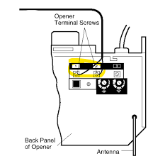
Step 4: Wire the Wall Control
- Run low-voltage wires (usually red and white)
- Connect to terminals labeled “RED” and “WHITE”
Step 5: Install Safety Sensors
- Place sensors 6 inches above ground on both sides
- Connect wires to sensor terminals
- Align sensors until LED lights are steady
Step 6: Test the System
- Restore power
- Press wall control
- Check door movement and sensor response
Common Wiring Problems and How to Fix Them
1. Door Doesn’t Respond
- Check power connection
- Verify wiring to wall switch
2. Sensors Not Working
- Misaligned sensors
- Loose wiring
3. Opener Runs but Door Doesn’t Move
- Motor connected incorrectly
- Mechanical issue (not wiring)
Wiring Safety Tips You Should Never Ignore
Electrical safety is critical when working with garage systems.
Important Guidelines
- Always turn off power before wiring
- Use insulated tools
- Avoid exposed wires
- Follow local electrical codes
For deeper understanding of wiring principles, you can refer to Wikipedia for general electrical system basics.
Craftsman Wiring: Pros vs Cons
Advantages
- ✅ Easy to understand with diagram
- ✅ DIY-friendly installation
- ✅ Widely available replacement parts
Disadvantages
- ❌ Requires basic electrical knowledge
- ❌ Mistakes can cause system failure
- ❌ Model variations may differ
Expert Insights: Why Proper Wiring Matters
Professional technicians emphasize that correct wiring ensures:
- Longer equipment lifespan
- Reduced repair costs
- Improved safety
A case study from home maintenance professionals shows that proper installation reduces repair calls by up to 35% within the first year.
Tips to Read Wiring Diagrams Easily
If you’re new to diagrams, follow these tips:
- Start from the power source
- Follow lines step by step
- Identify symbols before connecting wires
- Double-check every connection
Think of it like a roadmap—each line leads to a destination.
FAQ: Craftsman 1/2 HP Garage Door Opener Wiring Diagram
1. Where can I find the official wiring diagram?
You can find it in the user manual or printed inside the motor unit cover.
2. Can I install the wiring myself?
Yes, if you follow safety guidelines and instructions carefully.
3. What voltage does the opener use?
Most Craftsman openers use 120V AC power.
4. Why are my safety sensors blinking?
This usually means:
- Misalignment
- Dirty lenses
- Loose wiring
5. Do all Craftsman models use the same wiring diagram?
No. Wiring may vary slightly depending on model and year.
6. What tools do I need for wiring?
- Screwdriver
- Wire stripper
- Voltage tester
- Electrical tape
Conclusion
Understanding the Craftsman 1/2 HP garage door opener wiring diagram is key to a safe and successful installation. With the right steps, tools, and precautions, you can handle the wiring yourself and avoid costly professional repairs.
Take your time, double-check connections, and prioritize safety at every step.
If this guide helped you, feel free to share it on social media to help others confidently wire their garage door openers! 🚪⚡
Leave a Reply